
OpenSCAD用户手册/3D 基础模型
立方体
[编辑]在第一卦限中创建一个立方体。当center参数为true, 立方体中心点位于原点。如果按下列顺序输入参数,则参数名可写可不写。
cube(size = [x,y,z], center = true/false);
cube(size =  x ,     center = true/false);
- 参数:
- size
- 单个值, 立方体所有边以此为边长
- 3值数组[x,y,z], 立方体在x、y、z三个维度上的长度.
- center
- false (默认值), 立方体位于第一卦限中(3个坐标轴正轴围成的空间), 且一个角位于点(0,0,0)
- true, 立方体的中心位于点(0,0,0)
- size
默认值: cube(); 等效实现: cube(size = [1, 1, 1], center = false);
- 示例:

本例的几种等效实现脚本
 cube(size = 18);
 cube(18);
 cube([18,18,18]);
 .
 cube(18,false);
 cube([18,18,18],false);
 cube([18,18,18],center=false);
 cube(size = [18,18,18], center = false);
 cube(center = false,size = [18,18,18] );

本例的几种等效实现脚本
 cube([18,28,8],true);
 box=[18,28,8];cube(box,true);
球体
[编辑]在坐标系的原点处创建一个球体。参数名r可写可不写。若要以(直径)d取代(半径)r, 则必须写参数名d。
参数
- r
- 半径。此为球体的半径。球体的分辨率基于球体的大小与$fa、$fs、$fn三个变量。至于这些特殊变量的更多信息请查阅: OpenSCAD用户手册/其他语言特性
- d
- 直径。此为球体的直径。
- $fa
- 以度数来表示的片段角度。
- $fs
- 以毫米(mm)表示的片段尺寸。
- $fn
- 分辨率
默认值: sphere(); 等效实现: sphere($fn = 0, $fa = 12, $fs = 2, r = 1);
用例
sphere(r = 1);
sphere(r = 5);
sphere(r = 10);
sphere(d = 2);
sphere(d = 10);
sphere(d = 20);
// 这将创建半径为2mm的高分辨率球体
sphere(2, $fn=100);
// 这同样将创建半径为2mm的高分辨率球体,
// 但是此球体的极点上却没有那么多的小三角形
sphere(2, $fa=5, $fs=0.1);

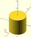
圆柱体
[编辑]绕z轴创建一个圆柱体或一个圆锥体。当center为true时,它将垂直居中于z轴。
如果将参数按如下顺序给出,则参数名可写可不写。如果填写了其中一个参数名,那么也要列出位于其后的参数名。
请注意: 如果要使用r, d, d1或d2,就一定要列出其参数名。
cylinder(h = height, r1 = BottomRadius, r2 = TopRadius, center = true/false);
- 参数
- h : 圆柱体或圆锥体的高。
- r : 圆柱体的半径。r1 = r2 = r。
- r1 : 圆锥体的底面半径。
- r2 : 圆锥体的顶面半径。
- d : 圆柱体的直径。r1 = r2 = d / 2. [请注意: 需要使用版本 2014.03]
- d1 : 圆锥体的底面直径。r1 = d1 / 2. [请注意: 需要使用版本 2014.03]
- d2 : 圆锥体的顶面直径。r2 = d2 / 2. [请注意: 需要使用版本 2014.03]
- center
- false (默认值),z轴的取值范围为0至h
- true, z轴的取值范围为-h/2至+h/2
- $fa : 每个片段的最小角度(以角度来表示)。
- $fs : 每个片段的最小圆周长度。
- $fn : fixed number of fragments in 360 degrees. Values of 3 or more override $fa and $fs
- $fa, $fs and $fn must be named. 点击这里来查阅更多细节。
默认值: cylinder(); 等效实现: cylinder($fn = 0, $fa = 12, $fs = 2, h = 1, r1 = 1, r2 = 1, center = false);

等效脚本
 cylinder(h=15, r1=9.5, r2=19.5, center=false);
 cylinder(  15,    9.5,    19.5, false);
 cylinder(  15,    9.5,    19.5);
 cylinder(  15,    9.5, d2=39  );
 cylinder(  15, d1=19,  d2=39  );
 cylinder(  15, d1=19,  r2=19.5);

等效脚本
 cylinder(h=15, r1=10, r2=0, center=true);
 cylinder(  15,    10,    0,        true);
 cylinder(h=15, d1=20, d2=0, center=true);
-
 center = false
 -
 center = true


等效脚本
 cylinder(h=20, r=10, center=true);
 cylinder(  20,   10, 10,true);
 cylinder(  20, d=20, center=true);
 cylinder(  20,r1=10, d2=20, center=true);
 cylinder(  20,r1=10, d2=2*10, center=true);
- use of $fn
$fn值越大,创建的表面就越圆滑,当然,渲染花费的时间也就越长。在开发过程中为了渲染更快可取适中值,待最终渲染(F6)时再采用较大值。
然而,在取较小值时,却会生成一些有意思的非圆形对象。以下几个示例会演示这一点:


scripts for these examples
 cylinder(20,20,20,$fn=3);
 cylinder(20,20,00,$fn=4);
 cylinder(20,20,10,$fn=4);
- undersized holes
When using cylinder() with difference() to place holes in objects, the holes will be undersized. This is because circular paths are approximated with polygons inscribed within in a circle. The points of the polygon are on the circle, but straight lines between are inside. To have all of the hole larger than the true circle, the polygon must lie wholly outside of the circle (circumscribed). Modules for circumscribed holes

精确度的相关注解
圆形对象都是以近似方式表示的。The algorithm for doing this matters when you want 3d printed holes to be the right size. Current behavior is illustrated in a diagram . Discussion regarding optionally changing this behavior happening in a Pull Request
多面体
[编辑]多面体是一种最常用的3D图元实体。可用它来创建任意具有凸凹(concave as well as convex)特性的规则或不规则形状几何体。而曲面则是由一系列平面近似构成。
polyhedron( points = [ [X0, Y0, Z0], [X1, Y1, Z1], ... ], triangles = [ [P0, P1, P2], ... ], convexity = N);   // 2014.03版本以前
polyhedron( points = [ [X0, Y0, Z0], [X1, Y1, Z1], ... ], faces = [ [P0, P1, P2, P3, ...], ... ], convexity = N);   // 2014.03及其后续版本
- 参数
- points
- Vector of 3d points or vertices. Each point is in turn a vector, [x,y,z], of its coordinates.
- Points may be defined in any order. N points are referenced, in the order defined, as 0 to N-1.
- points
- triangles [废止: triangles 将从未来发行版中去掉。 Use faces parameter instead]
- Vector of faces which collectively enclose the solid. Each face is a vector containing the indices (0 based) of 3 points from the points vector.
- faces [请注意: 需要使用版本 2014.03]
- Vector of faces which collectively enclose the solid. Each face is a vector containing the indices (0 based) of 3 or more points from the points vector.
- Faces may be defined in any order. Define enough faces to fully enclose the solid, with no overlap.
- Points which describe a single face must all be on the same plane.
- faces [请注意: 需要使用版本 2014.03]
- convexity
- Integer. The convexity parameter specifies the maximum number of faces a ray intersecting the object might penetrate. This parameter is only needed for correctly displaying the object in OpenCSG preview mode. It has no effect on the polyhedron rendering. For display problems, setting it to 10 should work fine for most cases.
- convexity
默认值: polyhedron(); 等效实现: polyhedron(points = undef, faces = undef, convexity = 1);
All faces must have points ordered in the same direction . OpenSCAD prefers clockwise when looking at each face from outside inwards. The back is viewed from the back, the bottom from the bottom, etc..
- 示例1 利用多面体来生成立方体( [ 10, 7, 5 ] );


CubePoints = [
  [  0,  0,  0 ],  //0
  [ 10,  0,  0 ],  //1
  [ 10,  7,  0 ],  //2
  [  0,  7,  0 ],  //3
  [  0,  0,  5 ],  //4
  [ 10,  0,  5 ],  //5
  [ 10,  7,  5 ],  //6
  [  0,  7,  5 ]]; //7

CubeFaces = [
  [0,1,2,3],  // 底面
  [4,5,1,0],  // 前面
  [7,6,5,4],  // 顶面
  [5,6,2,1],  // 右面
  [6,7,3,2],  // 背面
  [7,4,0,3]]; // 左面

polyhedron( CubePoints, CubeFaces );
立方体底面的等价描述
  [0,1,2,3],
  [0,1,2,3,0],
  [1,2,3,0],
  [2,3,0,1],
  [3,0,1,2],
  // 两个未重叠的三角形
  [0,1,2],[2,3,0],
  [1,2,3],[3,0,1],
  [1,2,3],[0,1,3],
- 示例2 金字塔(以正方形为底座的锥体):

polyhedron(
  points=[ [10,10,0],[10,-10,0],[-10,-10,0],[-10,10,0], // 底座上的4个顶点
           [0,0,10]  ],                                 // 锥体顶点
  faces=[ [0,1,4],[1,2,4],[2,3,4],[3,0,4],              // 每个三角形面
              [1,0,3],[2,1,3] ]                         // 正方形底座上的两个三角形
 );
- 示例3 一个三棱柱:

   module prism(l, w, h){
       polyhedron(
               points=[[0,0,0], [l,0,0], [l,w,0], [0,w,0], [0,w,h], [l,w,h]],
               faces=[[0,1,2,3],[5,4,3,2],[0,4,5,1],[0,3,4],[5,2,1]]
               );

       // preview unfolded (do not include in your function
       z = 0.08;
       separation = 2;
       border = .2;
       translate([0,w+separation,0])
           cube([l,w,z]);
       translate([0,w+separation+w+border,0])
           cube([l,h,z]);
       translate([0,w+separation+w+border+h+border,0])
           cube([l,sqrt(w*w+h*h),z]);
       translate([l+border,w+separation+w+border+h+border,0])
           polyhedron(
                   points=[[0,0,0],[h,0,0],[0,sqrt(w*w+h*h),0], [0,0,z],[h,0,z],[0,sqrt(w*w+h*h),z]],
                   faces=[[0,1,2], [3,5,4], [0,3,4,1], [1,4,5,2], [2,5,3,0]]
                   );
       translate([0-border,w+separation+w+border+h+border,0])
           polyhedron(
                   points=[[0,0,0],[0-h,0,0],[0,sqrt(w*w+h*h),0], [0,0,z],[0-h,0,z],[0,sqrt(w*w+h*h),z]],
                   faces=[[1,0,2],[5,3,4],[0,1,4,3],[1,2,5,4],[2,0,3,5]]
                   );
       }

   prism(10, 5, 3);
Debugging polyhedra
[编辑]Mistakes in defining polyhedra include not having all faces with the same order, overlap of faces and missing faces or portions of faces. As a general rule, the polyhedron faces should also satisfy (manifold conditions):
- exactly two faces should meet at any polyhedron edge.
- if two faces have a vertex in common, they should be in the same cycle face-edge around the vertex.
The first rule eliminates polyhedron like two cubes with a common edge and not watertight models; the second excludes polyhedron like two cubes with a common vertex.
When viewed from the outside, the points describing each face must be in the same order . OpenSCAD prefers CW, and provides a mechanism for detecting CCW. When the thrown together view (F12) is used with F5, CCW faces are shown in pink. Reorder the points for incorrect faces. Rotate the object to view all faces. The pink view can be turned off with F10.
OpenSCAD allows, temporarily, commenting out part of the face descriptions so that only the remaining faces are displayed. Use // to comment out the rest of the line. Use /* and */ to start and end a comment block. This can be part of a line or extend over several lines. Viewing only part of the faces can be helpful in determining the right points for an individual face. Note that a solid is not shown, only the faces. If using F12, all faces have one pink side. Commenting some faces helps also to show any internal face.

CubeFaces = [
/* [0,1,2,3],  // bottom
   [4,5,1,0],  // front */
   [7,6,5,4],  // top
/* [5,6,2,1],  // right
   [6,7,3,2],  // back */
   [7,4,0,3]]; // left
After defining a polyhedron, its preview may seem correct. The polyhedron alone may even render fine. However to be sure it is a valid manifold and that it will generate a valid STL file, union it with any cube and render it (F6). If the polyhedron disappears, it means that it is not correct. Revise the winding order of all faces and the two rules stated above.
Mis-ordered faces
[编辑]- Example 4 a more complex polyhedron with mis-ordered faces
When you select 'Thrown together' from the view menu and compile the design (not compile and render!) you will see a preview with the mis-oriented polygons highlighted. Unfortunately this highlighting is not possible in the OpenCSG preview mode because it would interfere with the way the OpenCSG preview mode is implemented.)
Below you can see the code and the picture of such a problematic polyhedron, the bad polygons (faces or compositions of faces) are in pink.
// Bad polyhedron
polyhedron
    (points = [
	       [0, -10, 60], [0, 10, 60], [0, 10, 0], [0, -10, 0], [60, -10, 60], [60, 10, 60],
	       [10, -10, 50], [10, 10, 50], [10, 10, 30], [10, -10, 30], [30, -10, 50], [30, 10, 50]
	       ],
     faces = [
		  [0,2,3],   [0,1,2],  [0,4,5],  [0,5,1],   [5,4,2],  [2,4,3],
                  [6,8,9],  [6,7,8],  [6,10,11], [6,11,7], [10,8,11],
		  [10,9,8], [0,3,9],  [9,0,6], [10,6, 0],  [0,4,10],
                  [3,9,10], [3,10,4], [1,7,11],  [1,11,5], [1,7,8],
                  [1,8,2],  [2,8,11], [2,11,5]
		  ]
     );

A correct polyhedron would be the following:
polyhedron
    (points = [
	       [0, -10, 60], [0, 10, 60], [0, 10, 0], [0, -10, 0], [60, -10, 60], [60, 10, 60],
	       [10, -10, 50], [10, 10, 50], [10, 10, 30], [10, -10, 30], [30, -10, 50], [30, 10, 50]
	       ],
     faces = [
		  [0,3,2],  [0,2,1],  [4,0,5],  [5,0,1],  [5,2,4],  [4,2,3],
                  [6,8,9],  [6,7,8],  [6,10,11],[6,11,7], [10,8,11],
		  [10,9,8], [3,0,9],  [9,0,6],  [10,6, 0],[0,4,10],
                  [3,9,10], [3,10,4], [1,7,11], [1,11,5], [1,8,7],
                  [2,8,1],  [8,2,11], [5,11,2]
		  ]
     );
Beginner's tip:
If you don't really understand "orientation", try to identify the mis-oriented pink faces and then invert the sequence of the references to the points vectors until you get it right. E.g. in the above example, the third triangle ([0,4,5]) was wrong and we fixed it as [4,0,5]. Remember that a face list is a circular list. In addition, you may select "Show Edges" from the "View Menu", print a screen capture and number both the points and the faces. In our example, the points are annotated in black and the faces in blue. Turn the object around and make a second copy from the back if needed. This way you can keep track.
Clockwise Technique:
Orientation is determined by clockwise circular indexing. This means that if you're looking at the triangle (in this case [4,0,5]) from the outside you'll see that the path is clockwise around the center of the face. The winding order [4,0,5] is clockwise and therefore good. The winding order [0,4,5] is counter-clockwise and therefore bad. Likewise, any other clockwise order of [4,0,5] works: [5,4,0] & [0,5,4] are good too. If you use the clockwise technique, you'll always have your faces outside (outside of OpenSCAD, other programs do use counter-clockwise as the outside though).
Think of it as a Left Hand Rule:
If you hold the face and the fingers of your right hand curls is the same order as the points, then your thumb points outwards.

Succinct description of a 'Polyhedron'
* Points define all of the points/vertices in the shape.
* Faces is a list of flat polygons that connect up the points/vertices.
Each point, in the point list, is defined with a 3-tuple x,y,z position specification. Points in the point list are automatically enumerated starting from zero for use in the faces list (0,1,2,3,... etc).
Each face, in the faces list, is defined by selecting 3 or more of the points (using the point order number) out of the point list.
e.g. faces=[ [0,1,2] ] defines a triangle from the first point (points are zero referenced) to the second point and then to the third point.
When looking at any face from the outside, the face must list all points in a clockwise order.
Point repetitions in a polyhedron point list
[编辑]The point list of the polyhedron definition may have repetitions. When two or more points have the same coordinates they are considered the same polyhedron vertex. So, the following polyhedron:
points = [[ 0, 0, 0], [10, 0, 0], [ 0,10, 0],
          [ 0, 0, 0], [10, 0, 0], [ 0,10, 0],
          [ 0,10, 0], [10, 0, 0], [ 0, 0,10],
          [ 0, 0, 0], [ 0, 0,10], [10, 0, 0],
          [ 0, 0, 0], [ 0,10, 0], [ 0, 0,10]];
polyhedron(points, [[0,1,2], [3,4,5], [6,7,8], [9,10,11], [12,13,14]]);
define the same tetrahedron as:
points = [[0,0,0], [0,10,0], [10,0,0], [0,0,10]];
polyhedron(points, [[0,2,1], [0,1,3], [1,2,3], [0,3,2]]);